 ABC's of Capacitors - Capacitor Tips for Tube Radios
CAPACITOR TIPS for the beginner. If you are new to restoring
antique tube radios here are some useful
CAPACITOR TIPS. How to choose capacitors and install them in tube radios is explained in non-technical
language. We hope you find this capacitor advice useful re your vintage radio repairs and restorations.


Capacitor Tips ( for the beginner ) :
Tube Radio CAPACITOR Basics
Your vintage tube radio needs both direct current (DC) and alternating currents (AC) to operate. Capacitors act to pass AC while blocking DC. Capacitors are used to block, pass, filter and tune the various currents in your radio.
- Don't let terminology confuse you….."condenser" is just an old fashioned name for "capacitor". If you're not the best speller, a condenser, capacitar, capaciter, capacitor, condensar and condensor are also the same.
- Capacitors have a capacitance value and a voltage rating. The capacitance value is a measure of how much electric charge a capacitor can store. The voltage rating is the maximum voltage the capacitor can handle without breaking down. This is sometimes expressed as WVDC (Working Voltage Direct Current).
- Your old tube radio uses 4 types of capacitors: variable (tuning) capacitors, mica capacitors, paper capacitors and electrolytic (filter) capacitors. When you restore an antique radio you will replace the paper and electrolytic capacitors, but not the variable and mica capacitors.
- In radio service parts lists and schematics, paper and electrolytic capacitors are usually expressed in terms "microfarads". Short forms for microfarad include mfd, MFD, MF, UF and uF. The mica capacitors in your tube radio will have lower capacitance values than the paper and electrolytic capacitors. Micas are expressed in terms of micromicrofarads (picofarads). Short forms for micromicrofarads include mmfd, MMFD, MMF, PF and pF. A pF is one-millionth of a uF. For example, a mica capacitor valued at 500 mmfd (pF) would be 0.0005 mfd (uF).
When reading schematics and buying capacitors, you sometimes have to be able to convert uF to pF or pF to uF. For your convenience we have a
Capacitor uF-nF-pF Conversion Chart
that you can refer to. You may want to tape this conversion chart to your workbench.
- As a general rule, if a capacitor in your vintage tube radio is less than 0.001 uF, it is probably a mica capacitor. If it is between 0.001 uF and 1.0 uF it is likely a paper capacitor and if it's more than 1 uF it's probably an electrolytic capacitor.
- Size wise, the electrolytics are the largest capacitors and most tube radios use 2 or 3 of them. The original electrolytic capacitors are typically the size of a roll of quarters or larger. On the old AC sets they are usually encased in aluminum and mounted on top of the chassis. With the lightweight AC/DC sets of the 1950's they are quite often under the chassis and may have a cardboard case.
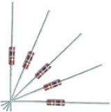
- The original paper capacitors in your radio will likely be in a brown paper tubular case (sometimes coated with wax). They are usually 1 to 1 1/2 inches long and 1/4 to 1/2 inches in diameter.
- Mica capacitors come in different sizes and shapes, but the most common shape is square or rectangular….brown in color with colored dots (sort of look like "dominos").
- Capacitors have either "radial" leads or "axial" leads. With "radial" type, both leads exit from the same end of the capacitors. With "axial" type, there is a lead at each end of the capacitors.

 Both types are equally good. Just be sure the capacitors you order have long leads.
- On schematic diagrams
the flat side of the capacitor symbol is the positive (+) side and the curved side is the negative (-) side. The positive end must be kept at the higher electrical potential (more positive voltage). Modern film capacitors are non-polar, so you don't have to worry about polarity when replacing old paper caps with new film capacitors.
- How about using NOS (New "Old Stock") capacitors? These are not recommended…use at own risk! As paper and electrolytic capacitors age their capacitance values drift, they dry out and they become leaky. Would you drive a 1930's automobile with NOS 70-year-old tires?
- Don't waste your money on audiophile, computer grade or tantalum capacitors. Sure they are good capacitors, but your old tube radio does not have the electronic circuitry to take advantage of those expensive capacitors. The only difference you will notice is a lighter wallet.
- Plastic / polyester film capacitors are now used in place of paper capacitors due to their smaller size, lower cost and superior performance. There are many variations of plastic / polyester capacitors.
Good types of film capacitors for tube radio restorations include metalized polyester, metalized polypropylene, metal-foil polypropylene, polystyrene and mylar. What is a Mylar? Mylar is simply the trade name of the synthetic film registered by duPont
- At higher frequencies polypropylene and polystyrene are more stable that polyester, so for film capacitors under 0.01 mfd, you may want to use polypropylene or polystyrene capacitors rather that polyester capacitors.
- What should it cost you to replace the capacitors in your radio? To "recap" a typical tube radio you will need two or three electrolytic capacitors, one or two line filter interference suppression safety capacitors and about a dozen film capacitors…..Total cost for these parts should be $20 or
less.
Non-Electrolytic CAPACITOR Tips
When replacing old paper/wax capacitors, you can't go wrong using film capacitors that have a higher voltage rating than the paper ones you are replacing. For example, if you are replacing a paper capacitor rated at 400 volts, you can use a 630-volt film capacitor (but not a 200-volt capacitor). A film capacitor with a higher voltage rating will give your tube radio better reliability and longer life.
Why were tube radios manufactured with 200, 400 and 600 volt paper capacitors if 600 volt could have been used for all the capacitors? Two reasons… cost and size. Capacitors used to be expensive so if a manufacture could use lower voltage capacitors in a circuit, it could cut production costs. Also, the higher the voltage the larger the paper capacitor, so it was easier to install lower voltage paper capacitors. Now-a days, film capacitors are inexpensive and compact, so use 630 volt film capacitors and you can't go wrong.
Radio Schematics and parts lists sometimes do not specify the working voltages of non-electrolytic capacitors. To be safe use a film capacitor rated at 630 volts.
Old paper/wax capacitors are one of the most unreliable parts in an old radio. Don't let "molded" paper capacitors fool you. They are just paper capacitors in plastic cases and are just as unreliable as the ones coated in wax. Molded paper caps were sold under trade-names such as Bumble Bee, Black Cats, Black Beauty, Pyamid, Goodall, etc.
Modern non-electrolytic capacitors i.e. mica capacitors, film capacitors, ceramic capacitors, etc are non-polar. This means you don't have to worry about which end to connect when replacing old paper capacitors with new film capacitors.

A typical old paper capacitor (top) can be replaced with either a new "axial" film capacitor (middle)
or a new "radial" film capacitor (bottom). As you can see ... modern day film capacitors
are much smaller than the old paper capacitors they replace.

As can bee seen above ... new mica capacitors are much smaller than the old "domino" style mica capacitors.
Although non-polar, old paper capacitors had black bands at one end. The black band indicated which end of the paper capacitor had some metal foil (which acted as a shield). The end with the metal foil was connected to the ground (or lowest voltage). The purpose of the foil shield was to make the paper capacitor last longer. When replacing these old paper caps with new film capacitors, you do not need to worry about which end goes to the lowest voltage side. On occasion you may hear someone claim that non-polar film caps must be installed in a certain direction to work properly in a vintage tube radio...this will only be true for those with an exceptional imagination....commonly known as the "placebo effect". This outer-foil topic has been beaten to death.
When replacing paper capacitors with film capacitors keep in mind that capacitance values are "easy to please". The uF value does not need to be exactly the same. For example; if replacing a 0.04 uF capacitor you can use a 0.039 uF; if replacing a 0.008 uF you can use 0.0082 uF. These replacements are virtually identical. If you are +/- 10% you be well within your radios factory specifications. (Just be sure your replacement capacitor has a working voltage is equal or greater than the original paper capacitor)
Electrolytic CAPACITOR Tips
Electrolytic capacitors are often referred to a "filter capacitors". Electrolytic capacitors help to convert (filter) AC (alternating current) power into the DC (direct current) voltage that your radio tubes need to operate.
Size wise, the electrolytics are the largest capacitors. On older sets they are usually encased in aluminum (can type) and mounted on top of the chassis. If they are not on top of the chassis you will find them under the chassis.

Modern day manufacturing technology has dramatically reduced the size of electrolytic capacitors.
Both the new axial electrolytic capacitor (top) and the old surface mount can capacitor (bottom) are 40uF 450V.
Capacitors used to be much larger and much more expensive than they are today. To save on space and cost "multiple section" electrolytics were used. These are simply two, three or four capacitors in the same case. You will notice just one ground connection/wire (usually a "black" wire) as all the caps share that ground. These "multi-section" caps can be replaced with single electrolytics. Modern electrolytics are compact and will easily fit under the chassis. You should leave the old can capacitor on the chassis for original appearance. Just be sure to disconnect it.

With their compact size three new Ecaps (right) can be easily be installed under the chassis
to replace the old multi-section (3 in 1) surface mount electrolytic capacitor.
Electrolytic capacitors work hard and are probably the most unreliable part of an antique radio. As they wear out (or simply get old) you get that famous "tube radio hum". Yes, in most cases it is bad filter capacitors that are the cause of that hum. WARNING! If you tube radio hums "turn it off and don't use it". Bad electrolytics are not only hard on your ears; they are hard on the tubes, transformers and other parts in your radio. Capacitors are cheap….tubes and other parts can be expensive and hard to find.
Electrolytic capacitors have a rated "working voltage" (WV) which is the voltage it can handle for a limited amount of time. Never use a Ecap with a working voltage equal or close to the actual voltage in the circuit. This is asking for trouble. Your car has a maximum RPM that the engine can operate at....if the max RPM is 6000RPM....how long will the engine last if you put the car in park and keep the engine reving at 6000RPM...yes, not long. An electrolytic capacitor should be operated no more than 3/4 of its maximum working voltage. This will both prolong capacitor life and allow some margin of safety for unexpected voltage surges. The higher the V the Ecap is worked at relative to the maximum working voltage the shorter will be the useful life of the Ecap. Never replace an electrolytic with one that has a lower voltage rating than the original Ecap.
As with paper capacitors, the capacitance value of an electrolytic capacitor is "easy to please", and an exact uF replacement is not necessary. For example, you can replace a 15 uF with a 16 uF or replace a 80 uF with a 82uF. If you can't find a close replacement …better to go with a higher uF value than a lower uF.
The old "rule of thumb" when replacing electrolytic capacitors is to not use more than 80% higher (or 20% lower) than "the original" uF size. If you replace an E-cap with one that has too high a MFD, the DC voltages will be higher than called for and your tubes and other parts will wear out faster. If you use too low a uF size, your radio will hum.
Warning ! Electrolytics have a negative end and a positive end…..if you install an electrolytic with the polarity mixed up not only will your radio not work…the electrolytic capacitor could explode. All the modern day electrolytic capacitors that JustRadios sells have an arrows (with negative signs) marked on them. This arrow with negative signs, points at the negative end of the electrolytic capacitor.

The arrow with the negative signs in it .... points at negative end of the electrolytic capacitor.
As a general rule AC (tube radios with power transformers) can use 450 volt electrolytics while lightweight ac/dc tube radios can use 160 volt filter capacitors. However, there are exceptions so always best to refer to a schematic.
Most Ecap manufacturers "very conservatively" tell us electrolytic capacitors have a shelf life of a couple of years, so make sure you are buying "fresh" stock electrolytics (not new "old stock"). Would you buy stale loaf of bread if a fresh one available?
Electrolytic capacitors should be stored at temperatures of 5 to 35 degrees C (40 to 95 degrees F) and in non-humid conditions (less than 60 relative humidity) to maximize shelf-life.
Don't put your tube radio into storage after you have restored the electric's. Once a month let the radio sing for a half-hour or so. This will prevent the electrolytic capacitors from drying out.
CAPACITOR Installation Tips
When restoring an antique radio it standard practice to replace certain of the radios capacitors. This is known as "recapping" a radio. An old radio may work with it's original caps….but for how long ?? ….and how safely ?? If the radio is going to be sold with a guarantee or is being given to someone as a gift, you should "recap" the radio.
You will want to replace all the paper and electrolytic capacitors. However, "do not replace the mica capacitors" if your radio was made in the USA or Canada. Mica capacitors found in American and Canadian radios very rarely go bad and if you replace them it will throw off the radios tuning. Replacing the mica capacitors will do more harm than good. Only replace a mica if you are sure it is bad (which is rare).
Mica Capacitor Discussion Update: As a member of the AVRS (Australian Vintage Radio Society) I receive the AVRS newsletter. As many of my customers have never had problems with mica capacitors, I was surprised and puzzled to read in the AVRS newsletter the advice "Mica Capacitors Connected to High Voltage Should be Replaced". I asked Warwick Woods (the current President of the AVRS) about this. Warwick was kind enough to reply with the below information.
Hello Dave,
The text was as follows:
"When restoring a valve radio treat all Mica capacitors that are connected
to high voltages, such as between anodes and earth, as potential faults and
replace them with a new mica component from the AVRS component store".
Many of the 'Simplex' brand Australian made Mica capacitors from the 1940's
and 50's suffer from silver migration through the mica and it appears that
this is due to porosity in the mica used at the time. If the outside
moulding is damaged or lets moisture through then the failure is
accelerated. When the silver finds its way through the mica, small
'whiskers' from either side make contact and can be blown away, (if
sufficient voltage or current is available), resulting in intermittent
crackling noises and other faults if high voltage finds its way into places
where it should not be.
The failure mode only occurs when one side of the capacitor is connected to
a high voltage and the other to a low potential point or ground.
As a general rule they need to be treated with suspicion and, to be on the
safe side, replaced.
I have heard some restorers from the US say that "I have never changed a
Mica in my life" and, while this may be an exaggeration, I have found that
quite old US made mica caps do not seem to suffer from the same problems as
our own ones. Maybe they used a different grade of mica in their
construction.
The dipped types that we purchase from you do not cause any problems.
Regards,
Warwick
Nov. 2014
After reading the above the mystery was solved. I had noticed that overseas customers were mush more likely to order mica capacitors than American customers. The need to replace a mica capacitors must depend on the quality of the original mica capacitor. Tube radios made in the USA and Canada which used high quality mica capacitors rarely go bad whereas the mica capacitors used in Australian, UK and other overseas radios must have been "not so great" these radios are much more likely to have mica capacitors in need of replacement.
Ceramic capacitors also very rarely go bad. Do not replace ceramic disc capacitors unless you are sure one has gone bad. Also, there are various types of ceramic capacitors with different operating properties. If a ceramic capacitor is a "general purpose/temperature stable" type it can be usually be replaced with a mica or film capacitor...but "temperature-compensating types" of ceramic caps should be replaced with same type.
Some radios use what are known as "line-filter" capacitors. These capacitors connect across your radios power line and/or go from your power line to ground. When replacing these capacitors, you should use special AC Rated Safety Capacitors. These special capacitors will improve the safety, performance and reliability of your radio. If you would like to learn more about these "safety capacitors", there is a link to the ABC's of Safety Capacitors near the bottom of this page.
Get a schematic (and parts list) before you start your recap job. It is often impossible to read the values that are on the original capacitors. Also, if the radio was repaired at some time in the past, there is a good chance someone threw in the wrong size capacitors, just to get the radio working. Without a schematic you'll be guessing.
Before replacing the capacitors, check all the radios' resistors. Since you will be replacing the capacitors, you should snip one lead of all the paper and electrolytic capacitors. Also remove all tubes. These steps will help prevent false resistance readings. In most instances resistors can then be measured in the circuit, without removing them.
All resistors that are off-spec should be replaced. What is off-spec? All resistors come with a “tolerance” such as 1%, 5%, 10%. The tolerance represents how close to the nominal/stated value a resistor should actually measure. For example a resistor with a nominal resistance of 1000 ohm and 10% tolerance (+/-10%) should measure somewhere between 900 ohms (the -10%) and 1100 ohms (the +10%). If the resistor does not measure within this range the resistor is said to be “out-of-tolerance” or "off-spec".
When it comes to tube electronics..."all resistors are not created equal".
Almost all types of resistors manufactured now-a-days are manufactured with either "small" size bodies or "normal" size bodies. “Small” body resistors have a lower working voltage than larger "normal" body size resistors. The common and cheaper "small" body type resistors (which are almost always rated at less than 350 volts) are fine for most transistor radios....but they can not handle 350V usually needed for tube radios. “Small" body resistors are cheaper to manufacturer and are lower priced than "normal" body type resistors. TIP: If you are restoring tube based electronics avoid "small" body type resistors. These cheap small bodied resistors are readily found on Ebay, Amazon and Websites that advertise they have the cheapest prices. As the saying goes..."you get what you pay for".
More information on resistors for tube electronics.
Resistor Size Tip: Don’t be fooled by resistors that are shown as M size on a schematic or parts list. Many years ago some manufacturers used M rather than K to represent 1000. For example if you see a resistor listed as 50M it is probably 50K (50,000 ohms as we depict sizes now-a-days). Examine resistor colour bars to confirm size if you are not sure if manufacturer used M rather than K.
Put
heat shrink (spaghetti) tubing
on the leads of the
capacitors and resistors before you solder them into the circuit.
This will help prevent dangerous shorts. If you need some heat
shrink tubing, just "let us know" and we will be glad to add some to your
capacitor order at no charge.
Always check a capacitor before installing it. Although it is very rare, every once in a blue moon, a new capacitor will be defective or off spec. Taking ten seconds to check a capacitor can save you hours of troubleshooting…..only to find out you accidentally installed a brand new "bad" capacitor.
If you need a higher uF than is available from your retailer, you can connect a couple of capacitors in parallel (side-by-side). For example if you need 200 uF at 450 volts you could connect two 100 uF / 450 volt capacitors in parallel and you would end up with 200 uF at 450 volts. You have kept the voltage the same while doubling the uF.
In "theory" connecting capacitors in series (end-to-end) should result in a higher working voltage. For example "in theory" two 100 uF at 450 volts in series should give you 50 uF at 900 volts (double the voltage and half the uF).....however, connecting capacitors in series is not recommended(& voids our guarantee) because with a series connection, one capacitor will usually end up getting more voltage than the other. This is because the leakage resistances of the two capacitors are rarely the same and the capacitor with the higher resistance will get a greater share of the voltage (which will often result in a series connected capacitor breaking down).
Please remember to always work safely. The high voltages stored in large capacitors can kill! If a radio has been turned on in recent weeks some of the capacitors (especially the electrolytic capacitors) may be holding deadly voltage charge. Before working with these capacitors they should be completely discharged. This can be come by (bridging) connecting the two ends the capacitor in question with a high wattage 1000 ohm resistor via insulated clips and leads.
Last but not least…where can one buy the right sizes and right types of capacitors needed
to restore a tube radio? You have found the right place….we are Dave and Babylyn Cantelon.
We specialize in Capacitors for vintage tube radios. Got a tube radio capacitor
question….email us at justradios@yahoo.com. Like to place a capacitor
order…here is our
Capacitor Shooping Cart.
.
About Us
: We are Dave and Babylyn
Cantelon and like yourself, we (well, at least one of us) like to restore old tube radios. We are also active
in a number of Vintage Radio Clubs (AWA, MARC, IARC, LVRC, OVRA, OVRC, CVRS), both north and south of the US/Canadian border. Check out our Radio Links
page if you would like to find a radio club to join. If you repair or restore old
tube radios you know it can be hard finding the right high voltage capacitors, capacitors with the right capacitance values
... capacitors with high working voltages and capacitors with long leads for hand wiring. We believe you will find
our capacitor product line useful re your antique tube radio repairs and restorations
Dave and Babylyn Cantelon of JustRadios
Email: justradios@yahoo.com
 Free World-wide Airmail Shipping
for all Capacitor KITS and
Resistor KITS
Free World-wide Airmail Shipping
for all Capacitor KITS and
Resistor KITS
 Single Section Can Electrolytic Capacitors - 500 Volts
Dual Section Can Electrolytic Capacitors - 500 Volts
Capacitor Clamps for Can Electrolytic Capacitors
RESISTORS for Tube Radios
ABC's of Safety Capacitors for Tube Radios.
Copyright Notice: This website and its content/webpages is Copyright 2014 David Cantelon (JustRadios)©. All rights reserved.
Any redistribution or reproduction of part or all of the contents in any form is prohibited other than the following: you may print or download to a local hard disk extracts for your personal use only. You may not, except with our express written permission, distribute or commercially exploit the content. Nor may you transmit it or store it in any other website or other form of electronic retrieval system.
This page last updated in January 2026.