 Auricap Capacitors for more than Just Radios
Auricap Capacitors for more than Just Radios
AURICAP APPLICATION / INSTALLATION NOTES
Auricap film capacitors
are not polarized. However, Auricaps have an outside foil
that is a very useful
noise shield when input and output impedances are considerably
different values and it is
connected to the lower impedance.
1) In all coupling
applications the input to the Auricap should be the black lead and
connected to the signal
source or circuit output with the red lead continuing on to the
next circuit input.
2) In all power supply
decoupling applications the outside foil or black lead should
be connected to ground and
the red lead connected to the voltage to be decoupled.
This is true for
decoupling either voltage polarities.
3) In loudspeaker
crossover applications, if the Auricap is in series, like feeding a
tweeter, the black lead
connects to the input binding post and the red lead connects to
the tweeter. Where the
Auricap is in parallel, as typically used for woofers, the black
lead connects to the
speaker connection that connects to the input binding post and the
red lead connects to the
other speaker terminal. Follow these same rules for midrange
connections where you will
have a combination of both.
The idea is to always have
the outside foil connected to the lower impedance to
provide outside foil
shielding to noise. Circuit outputs are always lower impedance
than inputs and should be
connected to the outside foil.
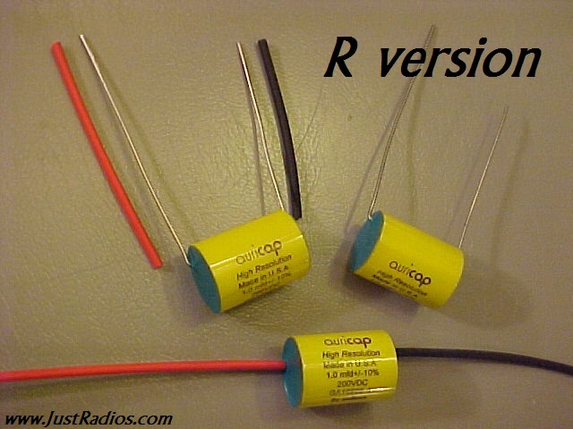
Auricap-R (R version) caps
have one lead longer than the other. The long lead is the
inside foil and to be
treated the same as the red lead on the standard axial Auricaps.
It follows that the shorter lead is the outside foil and functionally the same
as the black lead.
BYPASSING
Do not use bypass
capacitors in the signal path. A single capacitor for DC
blocking/AC coupling
creates a simple path with one time constant. The signal quality
will be compromised if a
bypass or multiple bypass capacitors are added to a signal
path capacitor. Bypass
capacitors were used in the past to bypass low quality film
capacitors or electrolytic
capacitors. The bypass was the lesser of two evils. With the
advent of better quality
film capacitors the need for a bypass capacitor was eliminated.
Bypass capacitors create
multiple signal paths with multiple time constants. These
time constants are very
short but they can still be heard as a smear or overall loss of
focus.
Always bypass power supply
capacitors. This maintains a low source impedance to
the power supply over a
wide bandwidth. If budget and space permit it is good to use
multiple value power
supply bypass capacitors with the smallest value being installed
directly
at the active device. (Tube or transistor.)
Note:
Some Auricap XO capacitors have two
red leads (rather than a black and red). In this
case one of the red leads will
have a black mark on it. This red lead “with the black mark”
should be treated same
as the Auricap black lead (outside foil) for installation purposes.